
AI search could not be completed. Please try again or adjust your search.
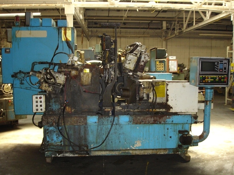
Cincinnati #220-8 Centerless Grinder
| Size Capacity | 4.5" | 4.5" |
220-8CINCINNATIMILACRON
WITH ACRAMATIC 725-G CONTROL
S/N3563A0185-0003Year:1985
STANDARD SPECIFICATIONS
WORK CAPACITY
Maximum work piece diameter…………………………………….. 4.5
Minimum work piece diameter…………………………………….. 0.060
GRINDING WHEEL
Maximum new wheel diameter……………………………………. 24
Minimum worn wheel diameter…………………………………… 17
Maximum wheel width……………………………………………....... 8
Wheel mounting hole diameter……………………………………. 12
GRINDING WHEEL SPEED
Surface speed………………………………………………………. 8500 ft/min.
(Maximum diameter wheel)……………………………………….. @ 1352RPM
GRINDINGWHEEL DRIVEMOTOR
256T Frame –1800RPM………………………………………….20 HP
Drive belts………………………………………………………… 3V850
GRINDING WHEEL DRESSER
Traverse drive motor (variable speed)…………………………….. 56C Frame
Worm gear reduce ratio…………………………………………… 10:1
Traverse rate (across wheel –IPM)………………………………… 1 to 30
Traverse rate (across wheel –mm/min)……………………………. 25, 4 to 762
Maximum traverse distance (across wheel)………………………... 12.5
Maximum profile depth…………………………………………….. 0.50
Diamond holder – single point type………………………………… 0.437Shank
Blade type diamond holder
Electric solenoid……………………………………………………. 0.0005Resolution
Optional stepping motor…………………………………………….0.00001Resolution
Maximum compensation (with stepping motor)……………………. 0.002
REGULATING WHEEL
Maximum new wheel diameter…………………………………….. 15
Minimum worn wheel diameter…………………………………….. 11
Mounting hole diameter……………………………………………..6
Maximum width…………………………………………………….. 8
Optional wheel width……………………………………………….. 10
MaximumRPM(during dressing)………………………………….. 300RPM
MinimumRPM…………………………………………………..…15RPM
Surface speed(ft/min)………………………………………………. 60 to 500
Surface speed(m/min)……………………………………………… 18, 3 to 152
Programmed surface speed is maintained constant as regulating wheel is dressed to smaller diameter.
Drive motor (variable speed)……………………………………….. 3.2 HP
Drive ratio…………………………………………………………… 8.333:1
Regulating wheel housing swivel (work feed angle)..……………… 8 DEGREE to 11/2 DEGREE
REGULATING WHEEL DRESSER
Traverse drive motor (variable speed)…………………………… 56C Frame
Worm drive reducer ratio………………………………………… 10:1
Traverse rate (across wheel –IPM)…………………………….... 1 to 30
Traverse rate (across wheel –mm/min)…………………………. 25,4 to726
Maximum traverse distance……………………………………… 11
Maximum profile depth………………………………………….. 0.50
Diamond holder –single point…………………………………...0.437Shank Diameter
Diamond compensator manual advance dial……………………...0.0005Division
Maximum compensation (with stepping motor)……………….… 0.002
Electric solenoid(optional)…………………………………….… 0.0005
Dresser swivel –degrees………………………………………… 8 DEGREE to 1 1/2-
TWO-WAY COMPENSATOR
Stepping motor……………………………………………………. 200 Steps /Revolution
Harmonic drive ratio……………………………………………… 160:1
Re-circulating ball screw………………………………………….. 8 mm Pitch
Compensator resolution…………………………………………… 0.00001
Positioning rate(maximum)………………………………………. 2.5 in/min.
IN FEED(Optional)
Stepping motor……………………………………………………. 200 Steps/Revolution
Harmonic drive ratio………………………………………………. 160:1
Re-circulating ball screw………………………………………….. 8 mm Pitch
Compensator resolution…………………………………………… 0.00001
Positioning rate(maximum)………………………………………. 2.5 in/min.
Rapid advance/retract distance(maximum)……………………….. 1.5
Rapid advance/retract rate…………………………………………. Fixed
Number of feed rates (plus gap eliminator rate)…………………… 3
Maximum feed rate (gap eliminator)………………………………. 2.5 in/min
Maximum feed rate (fast feed)…………………………………….. 2.5 in/min
Maximum feed rate (medium and slow feed)……………………… 0.9999 in/min
SWIVEL PLATE
Swivel to front (measured at adjustor)…………………………….. 0.50
Swivel to rear (measured at adjustor)……………………………… 0.50
Swivel indicator(division dialindicator)…………………………..0.0001
LOWER SLIDE
Maximum travel……………………………………………………. 9.05
Slide clamps(2)……………………………………………………. Manual
UPPER SLIDE
Maximum travel………………………………………………5.75
Slide clamps(2)……………………………………………… Manual
HYDRAULIC SYSTEM
Reservoir capacity…………………………………………… 29.5 gallon
Oil specification……………………………………………… CM P-38
Viscosity(S.U.S@ 100 DEGREE F)…………………………………. 149 to 182
ISO viscosity grade………………………………………….. ISO VG 32
Military spec. equivalent…………………………………….MIL-H-4600IA Type1
Pump capacity (without in feed)……………………………. 4.6 gallon permin.
Pump motor…………………………………………………1.5 HP 1800RPM
Frame……………………………………………………….145T,NemaC Face Mount
Pump capacity (with in feed)…………………………………8.8 gallon per min.
Pump motor………………………………………………… 3HP 1800RPM
Frame……………………………………………………….182T,NemaC Face Mount
Pressure filter……………………………………………….. Throw-Away Type Element
Bypass pressure…………………………………………….. 25PSI
Replacement element…………………………….CM No. 3634910 Schroeder No.CC3
Dual element filter (optional)
Main system pressure………………………………………. 300PSI
LUBRICATION SYSTEM
Reservoir capacity…………………………………………………….. 7.3 gallon
Oil specification……………………………………………………….CM P-47
Viscosity(S.U.S.@ 100 DEGREE F)…………………………………………... 317 to 389
ISO viscosity grade……………………………………………………. ISO VG 68
Military specification equivalent…………………MIL-L-46017 Type 1 Medium
System pressure…………………………………………………….… 300PSI
Lubrication cycle frequency………………………………………….. 5 Times Per Hour
System type: positive displacement, progressive series with cycle complete
pressure switch.
Distributor points:Grinding wheel dresser
Regulating wheel dresser
Swivel plate
Lower slide
Upper slide
In feed positive stop
Lubrication oil is also supplied at a constant pressure to the regulating wheel spindle bearings and drive unit.
Lubrication cycle frequency and points lubricated may vary due too optional/special equipment supplied.
CUTTING FLUID SYSTEM
Tank capacity……………………………………………………… 75 gallon
Pump capacity(flow)……………………………………………… 90 gallon per min.
Pump motor……………………………………………………….. 1/2 HP
Optional system…………………………………………………… Hydrant and sewer
Optional filter system…………………………………………….. Barnes Drill MPE-15
MACHINE WEIGHT
21,250 lbs.
Specifications are deemed accurate, however, subject to verification or prior sale
All exchange units/returns must be shipped within 30 days. All exchange units/returns must be shipped using DDP terms - Grinders Clearing House, Inc. dba GCH Machinery, is not responsible for any customs formalities or shipping costs.
If Grinders Clearing House, Inc. dba GCH Machinery does not receive exchange/core unit back within 30 days, GCH will invoice FULL replacement cost (OUTRIGHT Cost) to customer.

