
AI search could not be completed. Please try again or adjust your search.

Equipped With
Working Area
Pressure force
192.5 t
Brake length
122 in
Brake length
102 in
Throat
16 in
Stroke
8.1 in
Clear opening
19.09 in
Table width
4 in
Travels
Travel in X-axis
30 in
Feed
Bending speed
0.39 in/s
Rapid feed
5 in/s
Return speed
3.94 in/s
Drive Capacity
Motor rating main drive
24.8 Hp
Measures and Weights
Hydraulic tank volume
66 gal
Overall dimensions (length x width x height)
154x79x113 in
Weight
23,100 lbs
Part No.
423021
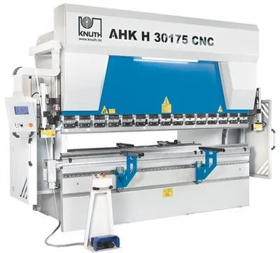
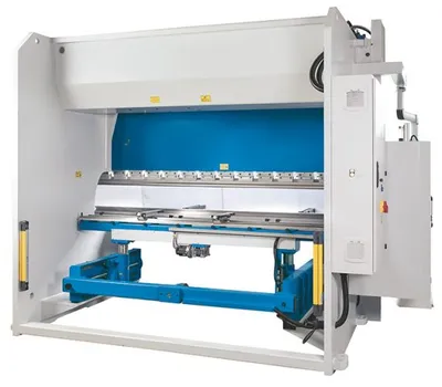
Machine Frame and Male Die
The machine frame is made of a high-precision, stress-relieved steel weldment
The machine frame has been machined on a state-of-the-art 5-axis milling machine in one single setup to ensure more precise bending and maximum reliability
All components subject to tensile loads have been carefully constructed and designed with large radii to eliminate the risk of welding cracks
Male die and table have been optimized to reduce deformations to the lowest minimum possible
The male die has been designed for optimum vertical load absorption by the guides, piston bearings and seals
All components were treated in a modern paint and drying system and feature two coats of paint, each coat with a minimum thickness of 60 micron
Work Area
A large throat, long stroke, and narrow table ensure plenty of free space to accommodate complex bending sequences
Crowning
All machines include a manual crowning system inside the table; a motorized crowning version is available as an option
The crowning provides a uniform distribution of bending forces to ensure precise bending angles across the full workpiece length
Hydraulics
Polished, hard chrome-plated pistons on both hydraulic cylinders feature superior 2 micron surface grades, ensuring a long seal life.
Cylinder bodies are forged from solid SAE 1040 material
Perfectly matched hydraulic components and measuring systems ensure exact synchronization of work cylinders
Back Gauge
The back gauge of a press brake is the most important factor for machining precision
The entire back gauge system is very robust and perfectly suited for rough production environments
Linear guides and large preloaded ball screws are mounted in a protective enclosure to ensure smooth operation even under the most difficult environmental conditions
Exact adjustment of back gauge finger height
Positioning of back gauge fingers on dual, smooth-running linear guides
Front Support Arms
Rigid linear guide and ball bearings for boom ensure maximum stability and easy positioning
Each support arm can be adjusted in height, is easy to handle and extremely sturdy
Bending Tools
Promecam (European) tool mounts accommodate an extensive selection of bending tools
All tools are hardened and ground, and allow precise setup
manual quick-action clamping system for tool mount shortens tool changing times
Safety and Productivity
Safety concept based on the latest CE standards
The manual AKAS Laser Safety System is known for excellent reliability and functionality without the limitations that are typical for light curtains
Cybelec Touch 8 2D Steuerung fŸr 3 Achsen
X-axis back gauge with servo motor
quick-action clamping of male die
manual akas laser safety LC II M FMSC safety system
light barrier
2 front support arms
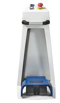
foot pedal with E-stop button
operator instructions
european type male die H = 3 inch
european type female die 4V H: 2 x 2 inch
2 height-adjustable back-gauge fingers
european tool mount
motorized crowning
R axis