

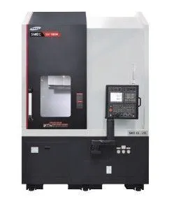
NEW SMEC SLV 800

Overview
Brand new SMEC SLV 800 CNC Lathe, 2024 model, ready to enhance your production capabilities. Ideal for precision and efficiency, this state-of-the-art equipment is perfect for modern machining needs.
Specs
MACHINE SPECIFICATIONS
CAPACITY
Swing over the bed 35.04”
Swing over the cross slide 29.13”
Maximum turning diameter 32.68”
Maximum turning length 31.50”
SPINDLE
Chuck size 18” (15” / 21” / 24” – Opt.)
Spindle nose A2-11 (ASA)
Main spindle motor (Duty / Cont.) 50 / 40 hp
Spindle speed 2,000 rpm
Spindle bearing diameter (front) 6.29"
Spindle torque (Max) 1937.57 ft.-lbs.
Speed ranges 2 Speed gear
SLIDE & CARRIAGE
X Axis travel 16.93”
Z Axis travel 31.50”
Rapid traverse X 787 ipm
Rapid traverse Z 787 ipm
Guide ways (X / Z) Box way
Ballscrew diameter (X / Z) 1.57” / 1.97”
Axis feed thrust, Continuous (X / Z) 2,797 lbs. / 4,831 lbs.
Repeatability (X / Z) ±0.00008” / ±0.00012”
TURRET
Number of tool stations 12 Tools (BMT75)
Turret indexing speed 1 station 0.3 seconds
Curvic coupling 3 Piece hydraulic clamp / Servo index
Coupling diameter / clamp force 7.87” / 17,776 lbs.
Tool size (turning and facing) 1-1/4” – Wedge clamp
Tool size (boring bar maximum diameter) 2-1/2”
Turret Index repeatability ±0.00012”
MACHINE SIZE
Floor space requirements (L x W x H) (without CC) 88” x 169” (138”) x 138”
Machine weight 24,251 lbs.
Power consumption 62 kVA
Voltage 220V±10%, 60 Hz, 3 phase
CNC
CNC model Fanuc 0i-TF PLUS
Display unit 15” TFT LCD Color Monitor
SHIPPING DIMENSIONS (L x W x H, Weight)
Crate #1 (Machine) 150” x 91” x 148”, 26,455 lbs.
Crate #2 (Chip Conveyor) 150” x 30” x 70”, 3,968 lbs.
MACHINE CONSTRUCTION & FEATURES
One-piece Meehanite® cast iron bed
Box way construction with anti-friction mating way surfaces
Anti-heat displacement spindle and headstock design
Ultra-precision and high rigidity spindle bearings
Powerful and reliable Fanuc motors and drives system
High precision pre-tensioned ball screws
12 Station rigid turret design with high accuracy indexing and rigid curvic coupling
Electric torque limiter protects ball screws
Separate coolant system
Metered piston distributor lubrication
Way lube separation system
STANDARD EQUIPMENT
Machine work light
Complete coolant system
Chip and coolant splash guarding (full coverage)
Hydraulic unit
12 Position servo turret
Lubrication system
Chuck foot switch
Hydraulic pressure interlock from main hydraulic line
Foundation kit (plates only)
One (1) set of adjusting tools
Machine Manuals: one (1) each (Electrical, Maintenance, Parts List, Operation / Maintenance)
Fanuc Machine Manual: one (1) each (Manual Guide i, Operators, Maintenance, Operators volumes 1 and 2) in USB
STANDARD TOOLING PACKAGE
Face Holder (1-1/4”) 1 pc.
O.D. Extension Holder (1-1/4”) 5 pcs.
Boring Bar Holder (2-1/2”) 5 pcs.
U-Drill Holder (2-1/2”) 1 pcs.
Boring Bar Sleeve (5/8”) 1 pc.
Boring Bar Sleeve (3/4”) 1 pc.
Boring Bar Sleeve (1”) 1 pc.
Boring Bar Sleeve (1-1/4”) 1 pc.
Boring Bar Sleeve (1-1/2”) 1 pc.
Boring Bar Sleeve (2”) 1 pc.
Drill Socket MT #3 1 pc.
Drill Socket MT #4 1 pc.
Drill Socket MT #5 1 pc.
FANUC 0i-TF PLUS CONTROL SPECIFICATIONS
TYPE OF CONTROL
32-Bit Multi-Processor Continuous Path Control
HARDWARE COMPONENTS
15” Color TFT LCD Screen
PMCIA Flash Memory Card Interface
USB Port
Ethernet Port
RS232 Interface
110V AC outlet
SCREEN DISPLAY
Window Oriented Operator Interface
Display of Current Block and Position Check Screen During Program Execution
Screen Texts: English (24 additional languages available)
Machine, Absolute, Relative, and Distance to Go Position Display
Spindle Speed / Feed Rate Display
Spindle / Servo Load Monitor
Current Alarm / Alarm History Display
OPERATION
Program Protection on Machine Control Panel
512Kbyte Part Program Storage
400 Part Programs Storage
Built In Run Hour / Parts Counter / Cycle Time Display
Tool Life Management
Tool Measurement Compensation (with Tool Presetter)
Background Editing
Help Function
Graphic Display
1 Position Spindle Orientation
Optional Block Skip
Program Restart
Offset Guard Function
Rigid Tapping
Automated ZRN Function
MODES
Automatic
Control of Automatic Mode by:
- Feed Hold / Cycle Stop
- Block Skip
- Single Block
- Optional Stop
- Dry Run
- Machine Lock
Jog
MDI (Manual Data Input)
Edit
MACHINE CONFIGURATION FOR AXES
Inch or Metric Programming
Switching Between Metric and Inch for Input and Offsets, Display, and Programmed Path
Feed rate and Rapid Traverse: Minimum Input Feed rate in Inches / min = .0001 inches / min
Revolution Feed rate: Minimum Input Feed rate in Inches / Rev. = .0001 Inches / Rev.
MACHINE SPINDLE CONFIGURATIONS
Constant Spindle Speed and Constant Surface Speed Control
Programmable Maximum Spindle Speed Control
Thread Cutting: Thread Pitch Constant Minimum Pitch in Inches / Rev. = .0001 Inches / Rev.
OVERRIDES, OFFSETS AND COMPENSATIONS
Feed rate Override 0% to 150%
Rapid Override 0%, 25%, 50%, and 100% (0% is user adjustable)
Spindle Speed Override 50% to 120%
128 Pair Tool Offsets
Work Shift / Work Offsets (G54-G59)
Tool Nose Radius / Tool Geometry / Tool Wear Compensation
Backlash Compensation
CNC PROGRAMMING
Diameter / Radius Programming
Insert, Alter, Delete
Character, Program & Sequence Number Search
Cut, Copy, and Paste Function
Corner Chamfer C / Radius R Programming
Direct Drawing Dimension Programming
Absolute / Incremental Programming
Thread Chamfering On/Off
Mirror Image / Each Axis
Stored Stroke Check / 1st, 2nd, 3rd, and 4th Reference Return Positions
Skip Function (G31)
Sub-Program Call (10 Level Nest)
Variable Lead Threading (G34)
Turning Canned Cycles (G90-G94)
Multiple Repetitive Cycles Type I & II (G70-G76)
Drilling Cycles (G73, G75, G80-G89)
Circular Interpolation by R, I, J, K
Feed Per Minute (G98) / Feed Per Revolution (G99)
Programmable Data / Parameter Input
G-Code System A/B/C select
Custom Macro B / 600 User Variables
Thread Repair Function with Manual Guide i
SAFETY AND DIAGNOSTIC FUNCTIONS
Safety Routines Permanently Active for Measuring Circuits, Over Temperature, Battery,
Voltage, Memory, Limiting Switches, Hydraulic System, and Cooling Systems.
Self-Diagnostics
Servo Monitoring
Spindle Monitoring
Equipped With
Warranty
The machine is warranted against defects in parts, material and workmanship for a period of twelve (24) months after the date of installation. The control, servomotors and main spindle motor are warranted against defects in parts, material and workmanship for a period of twenty-four (24) months after the date of installation.
Installation
A certified engineer will supervise installation of the machine/control system. Initial training on machine/control operation and programming will also be done at the time of machine installation.
Delivery
Free on Board, Port of Entry, Duty paid. Please verify delivery status.
Tooling
We are giving you guys a chance to pick out from our inventory $5000.00 value
Terms
30% down, 60% at shipment, 10% net 30
Explore More New Equipment Listings on Equipt
Browse related New CNC Lathes, Lathes & Turning Machines, Metal Cutting, and Metalworking equipment, including SMEC machines for sale on Equipt.
New Equipment for Sale in Louisiana, United States
Find New CNC Lathes, Lathes & Turning Machines, Metal Cutting, and SMEC equipment for sale in Louisiana, United States, with related local Metalworking searches.
New Equipment for Sale in United States
Browse New CNC Lathes, Lathes & Turning Machines, Metal Cutting, and SMEC equipment for sale across United States, including related Metalworking inventory paths.
Sell Your Used Equipment
Find dedicated pages to sell used CNC Lathes, Lathes & Turning Machines, Metal Cutting, Metalworking, and SMEC equipment on Equipt.