

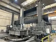
NEW 2019 EMSIL HVTL-60/80

Overview
2019 EMSIL HVTL-60/80 CNC,
1. MACHINE GENERAL DESCRIPTION
The Heavy Vertical Turning Lathe EMSIL HVTL-60/80 CNC is a CNC machine tool with a rotary faceplate and movable crossrail type construction and equipped with numerical FANUC control unit. The main parts of the machine such as the table, bed, columns, crossrail and Y axis beds are of special fabricated construction with an optimum structure distribution that allows for maximum resistance and stability.
The crossrail accommodates one massive RAM/Head Z axis vertical subassembly with live spindle. The table hydrostatic guiding technology allows a large working load capacity.
The crossrail moves up & down along the columns, and can be locked in the indexed working positions to optimize the best possible working cinematic.
The machine is equipped with a faceplate with C axis.
Overall the machine is manufactured with high tech modern technology, to secure the best possible level of accuracy & reliability with a minimum of maintenance, and particularly with:
• The linear X axis, transversal headstock movement, rack and double pinion reducer integrated in the saddle secure a long term low maintenance & stable system (mechanical preload).
• The linear Y axis, horizontal portal gantry movement, rack and double pinion reducer integrated in the saddle secure a long term low maintenance & stable system (mechanical preload).
• The linear Z axis, vertical RAM movement, ball screw with double preloaded nuts secure a long term low maintenance & stable system (mechanical preload), with hydraulic balance system through cylinders.
• The four direct drive motor-reducer system for table rotation drive, secure a long term low maintenance & stable system (electronic preload).
• The linear W axis vertical crossrail drive systems with double preloaded ball screws mechanism, in order to secure a better machining performances for long vertical machining passes, by avoiding the Z axis ram mechanical variation (deflection & vibrations) due to the RAM extension.
• The hydrostatic rotary table that secure a maximum axis drive & guiding efficiency, provide a superior vibration dampening effect, as well as a perfectly smooth movement especially in slow federate speed by elimination of “ slip-stick “ phenomena well known in traditional guiding technology for heavy duty machinery .
• The most modern electronic features like:
o Pressurized Heidenhain linear scales feedback on linear axis, X and Z;
o Heidenhain central rotary encoder for rotation speed monitoring;
o “Geometrical adaptive control”, “beam sag compensation“, special CNC feature“. On the top of ISO#3655 geometric acceptance.
2. BED & TABLE SUB-ASSEMBLY (FACEPLATE)
The table’s bed is made of massive heavy duty stress relieved fabrication to support the table. The axial bearing of the table is assured by means of a hydrostatic bearing the radial stability via a cross roller type radial-axial bearing.
This system is extremely advantageous especially for machining heavy work pieces with the following advantages:
It reduces the torque required for the spinning and starting of the table thus offering a much lower friction coefficient and consequently better drive power efficiency for the cutting processes;
It reduces the wear of the table and bed guideways;
It eliminates table vibrations leading to improved surface finish;
It secure a constant smooth cutting speed even at very low speed by eliminating the “slip-stick” phenomena existent on any other bearing technology;
The horizontal geometry of the table can be ultimately perfected with the help of the hydrostatic diagram method.
The main drive system is linked to a pressurized oil supply in order to secure for immediate & non conditional lubrication. In the unlikely event of lack of oil and the guide ways overheating are announced by means of optical and acoustic alarms - safety devices.
A high resolution central encoder Heidenhain secured the best level of feedback accuracy for C axis motion control for milling or positioning, as well as rotations speed monitoring for turning operations like threading or constant cutting speed.
The table is made of three (3) massive high quality fabricated sections
Table Rotation drive (turning) & C axis drive mechanism (milling)
The table is driven 4x40 kW FANUC asynchronous AC motors coupling with special type gearboxes.
For turning the four motors work together thus combining the power of the four.
For the milling operations, two motors act against the other two by creating a load while the primaries is loaded to the required capacity to turn the table in order to eliminate any possible backlash.
The lubrication is carried out by an automatic re-circulating system, with a pump.
A special central rotary encoder, Heidenhain make, is provided to measure the C axis positioning and a second encoder for continuous speed measuring.
Eight (8) clamping devices are provided to lock the table in any angular position for heavy milling or drilling operations.
3. COLUMNS & CROSSRAIL
The structure made of heavily ribbed massive and stress relieved fabrication in order to withstand high cutting forces with minimum deformations.
The vertical displacement of the crossrail’s guiding system is made of lubricated friction material and slides on two large size vertical slide ways one each column.
The vertical feed mechanism consists of:
Two vertical preloaded ball screw mechanism, supported by a special bearing, acted by a single asynchronous motors with feed reducers worm and worm wheel type(one each column).
On both columns there are indexing posts and the cross rail also has hydraulic clamping system for a tight rigidity.
Each indexing post has its own feedback limit switch.
Centralized lubrication unit for ball screw, bearings & slide ways: lost oil type, manufactured by Dropsa, with intermittent lubrication unit through low capacity injectors.
Crossrail static positioning mode: The cross rail can be positioned on the indexing seats and locked with a mechanic hydraulic locking device attached to the crossrail.
The crossrail’s X axis sub-assembly
Heavily ribbed and massive fabricated and stress relieved cross rail ensure a great rigidity and stability. The cross rail is fitted with:
three large size linear guide ways, size 65, to receive the X axis saddle, adjusted to the crossrail.
between the guide ways is a large size rack for the saddle drive with preloaded double pinion system reducer system for a backlash free functioning.
The X axis horizontal feedback Heidenhain linear scale is also adjusted to the crossrail between the guide ways.
Two mechanic hydraulic multi points locking device on the back side of the crossrail to secure the position of the crossrail in any indexed vertical position along the column slide ways.
The horizontal X axis linear guiding system is on linear guide ways, 3 pieces of size 65, and the saddle is provided with 12 preloaded carriages with rollers.
The horizontal X axis drive mechanism consists of:
AC servo moto-reducer with mechanical preload.
The reducer is fitted with preloaded double pinion system reducer for a backlash free functioning pinion that directly works on the X axis rack, which secures the best level of drive consistency and accuracy with the minimum level of maintenance.
One horizontal high resolution linear Heidenhain scale to secure the best level of feedback accuracy.
Centralized lubrication unit for racks, pinions and reducer, and also for the linear guide ways carriages: lost oil type, manufactured type Dropsa and with intermittent lubrication unit through low capacity injectors.
The cross rail is a box type unit providing high stiffness versus twisting and bending. The cross rail structure is supplied with a compensation beam that offers certain advantages:
Crossrail compensation method – Mechanical Compensation
By compensating the crossrail linearity, a high accuracy of the horizontal rail head displacement is assured on the crossrail.
The compensation beam makes unnecessary any special processing of the crossrail in order to achieve the correct linearity.
Crossrail compensation can be easily performed in case it is influenced by a long operation or temperature fluctuations.
Crossrail compensation method – Electronic Sag Compensation
On the top of the highest geometry acceptance standard (ISO-3655), the Electronic “Beam Sag compensation“ option allows to further perfected dynamically the straightness of the X axis displacement, as well as the squareness of with Z axis.
4. Y AXIS DRIVE (MOVING GANTRY)
The Y axis moving gantry will allow the machine to perform numerous milling operations on wide variety parts, and further optimized the full machining system efficiency & flexibility.
The Y axis subassembly is made in massive high quality stress relieved fabrication with large size (100) linear guide way, the Y axis saddle being provided with 12 preloaded carriages with rollers. Between the two guide ways is a large size rack for the saddle’s drive with preloaded double pinion system reducer system for a backlash free functioning.
5. RAM/TURNING AND MILLING HEAD (X and Z axes)
The saddle (X axis) in massive stress relieved fabrication moves horizontally (X axis) along the crossrail’s linear guideways on 12 preloaded roller carriages.
The X axis drive mechanism is foreseen with rack and double pinion as describe above, including horizontal feedback received by Heidenhain linear scale.
The RAM (Z axis), made in heavy duty, stress relieved fabrication part section 450 x 450 mm, moves vertically in its RAM housing on friction material guiding.
The vertical Z axis drive mechanism is achieved with a vertical preloaded ball screws mechanism supported by special bearings and an A.C. break servomotors with feed reducers offering a high precision in the positioning of the RAM.
The vertical Z axis feedback with high resolution linear Heidenhain scale provides the best level of feedback accuracy.
One hydraulic counterbalance system with one cylinder is supplied in order to counterweight the RAM’s sub-assembly.
Lubrication for ball screw & bearings and friction surfaces is performed by centralized lubrication unit, lost oil type, manufactured by Dropsa, with intermittent lubrication unit through low capacity injectors.
The Milling spindle
- Spindle main motor………………………................40 kW
- Spindle rotation :…………………………..................0-3000 rpm
- Spindle torque...............................................1200 Nm
- Spindle : …………………………………......................ISO #50 taper
- Automatic drawbar for automatic tool change from 60 positions tool changer
- Automatic Hydrodock system for tool change from 12 positions tool changer
- Coolant Through spindle or/and external
The milling RAM is prepared to pick up also turning tool in automatic way through the central ISO-50 clamping system and four additional HYDRODOCK systems in the corners plus the frontal HIRTH Couplings.
6. AXES GUIDEWAYS PROTECTION
The linear X, Y and W axes guideways will be protected by means of metallic telescopic covers.
The Z axis, the RAM, will be protected by means of scrapers.
7. HYDROSTATIC PROTECTION
In the unlikely event of case of sudden hydrostatic loss of power supply, the system is protected by double level of safety:
a) By oils accumulators on the hydrostatic unit to continue the hydrostatic supply on the axis the time the machine’s stops (particularly for the table rotation).
b) By hydrostatic Bronze plates guiding construction that minimize the potential damage created by a “hydrostatic landing”.
8. CNC CONTROL
The machine is equipped with FANUC 31i
Synchronized axes: 2 linear axes X and Z and 1 rotating C axis.
Portable Handheld unit;
PLC;
Numerous options.
The operator console for CNC and machining is conveniently located on the operator’s platform.
Push buttons for emergency stops are provided both on the central control desk, on the pendant control panel and on the electrical cabinet as well as an others strategic locations to secure maintenance or special operations. When one of these push buttons is depressed, a braking moment will be created at the main motor in order to rapidly stop the table and to interrupt the operational circuit, by stopping the driving motors excepting the hydrostatic oil supply.
9. ATC - AUTOMATIC 12 POSTS FOR TURNING TOOLHOLDERS
The accessory tool changer is located on the right side of the machine, fixed on the crossrail;
12 positions for toolholders or accessories.
10. ATC - AUTOMATIC 60 POSTS FOR MILLING TOOLS
The Milling tool changer is located on the left side of the machine , fixed on the crossrail;
Chain type;
60 positions for ISO-50 taper.
Specs
MAIN TECHNICAL FEATURES UNITS VALUES
Working Capacity
Work piece maximum diameter mm 8500
Distance between columns mm 8500
Work piece maximum dia. through gantry travel mm 12000
Work piece maximum height mm 6500
Work piece maximum weight on faceplate tons 100
Faceplate
Diameter mm 6000
Speeds range (continuously variable) rpm 0-50
Main FANUC motor (4 pieces) kW 160 (4 x 40)
Maximum torque available at the table Nm 470000
Crossrail
Vertical travel, W axis mm 5200
Feed range (continuously variable) mm/min. 250
Gantry
Horizontal travel Y axis mm 11800
Feeds range (continuously variable) mm 10000
Turning and Milling RAM
Vertical travel, Z axis mm 2700
Rapid feed on Z axis mm/min. 15000
RAM cross section mm 450x450
Milling motor power kW 40
Maximum milling speed rpm 3000
Milling spindle taper - ISO-50
Equipped With
Standard Accessories
CNC Fanuc
Fixed table 2000x6000 mm, 3 pieces
Heidenhain linear scales
Faceplate with 8 jaws
Chip conveyor system
Centralized hydraulic and lubrication units
Electric equipment (415V±10%; 50Hz±2%)
Levelling devices for foundation
Standard painting: RAL5015
Technical documentation, 1 copy, in English Language.
Explore More New Equipment Listings on Equipt
Browse related New Vertical Boring Mills (incld VTL), Boring Mills, Metal Cutting, and Metalworking equipment, including EMSIL machines for sale on Equipt.
New Equipment for Sale in Illinois, United States
Find New Vertical Boring Mills (incld VTL), Boring Mills, Metal Cutting, and EMSIL equipment for sale in Illinois, United States, with related local Metalworking searches.
New Equipment for Sale in United States
Browse New Vertical Boring Mills (incld VTL), Boring Mills, Metal Cutting, and EMSIL equipment for sale across United States, including related Metalworking inventory paths.
Sell Your Used Equipment
Find dedicated pages to sell used Vertical Boring Mills (incld VTL), Boring Mills, Metal Cutting, Metalworking, and EMSIL equipment on Equipt.